Inductive Centring System for air-cooled shakers
In order to correctly centre a shaker system so that sufficient stroke can be achieved and the overtravel safeguards work properly, a height control system is needed.
The Inductive Centring System, abbreviated ‘ICS’ and freely translated inductive centring system, is a new measurement method patented by Brüel & Kjaer to control the height of the fixture. This non-contact and inductive design is no longer affected by environmental factors and adjusts the luminaire position without the use of an optical eye and a target. The ICS is accurate to within 0.5mm for the most reliable tests.
The digital sensor in the measurement system makes regular calibration and sensor maintenance unnecessary. The ICS is maintenance-free, allowing you to run your tests with peace of mind. Users no longer have to wait for routine on-site service or calibration of the sensor.
Currently, the new shakers LDS V8 and V8900 are equipped with this new measurement method. For the LDS V8, LDS V875 also exists as a retrofit.
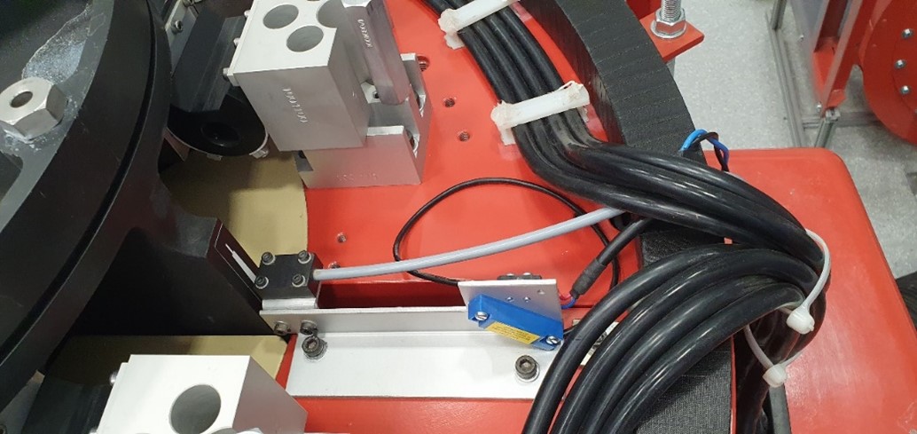
Picture 1: old system (CPS)
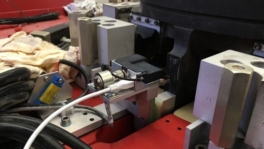
Picture 2: new system (IPS)
Installation
After the old CPS system is dismantled, the new ICS system is installed. An adapter block is placed on the armature with a Target Assembly mounted on it. Afterwards, the ICS Assembly is mounted on the body of the shaker.
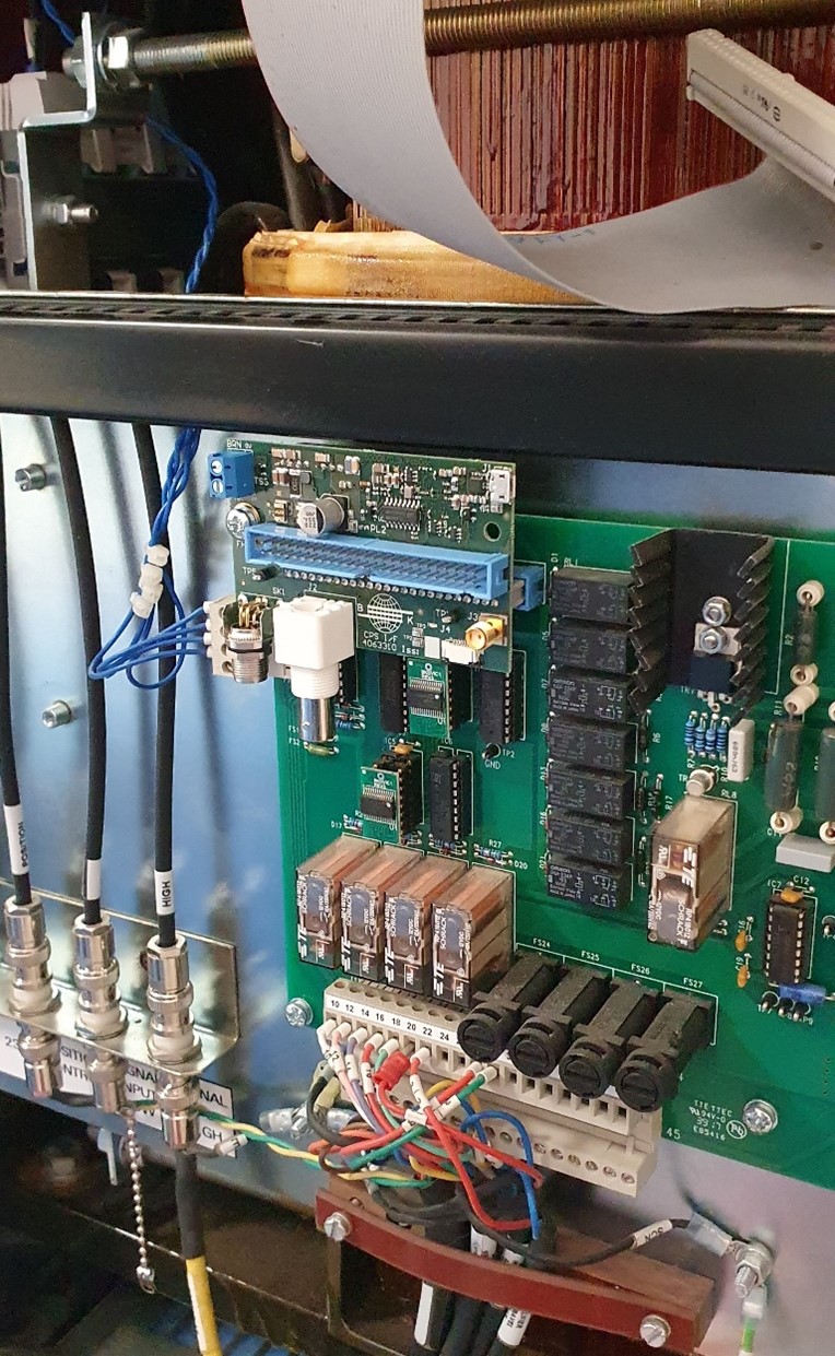
The next step is to adapt the amplifier by means of an Interface PCB. This comes on the existing PCB and allows the new system to communicate with the existing technology.
After installation, Alignment Jigs are placed on the fixture so that the fixture is nicely centred. This allows the ICS system to be tuned. To do this, one connects, via a laptop, to the ICS on the shaker. The module is then configured and new overload parameters are loaded.
After installation, the overtravel interlocks are tested to see if they still work. These interlocks are very important for the security of the shaker. Finally, an 80% test is performed to confirm that the specifications of the shaker system are still met.
Picture 3: new PCB
Learn more?
For more information please contact the ENMO Team or learn more via this link.

 ▽
▽
 English
 Nederlands


